

Critical Flow Factor, often referred to as “Cf” is a coefficient that defines how pressure will recover after it drops to its lowest point inside the control valve. This lowest point is also referred to as the vena contracta*.
All globe-style control valves have a Cf that stays consistent regardless of the trim position, unlike the Flow Coefficient (Cv).
Note: The Pressure Recovery Factor (FL) also refers to the Critical Flow Factor in some literature.
Cf is a factor needed in order to calculate Flow Coefficient (Cv) or Flow Rate for valve sizing purposes.
Valve Flow Coefficient (Cv) is a valve’s capacity for a liquid or gas to flow through it.
It is technically defined as “the volume of water at 60°F (in US gallons) that will flow through a valve per minute with a pressure drop of 1 psi across the valve.”
As the stem opens, the Cv increases.
The maximum Cv for the 2-inch regulator is 47, while the maximum for the 3-inch regulator is 117.
Cold Water Equivalent means the barrels of steam expressed in terms of an equivalent cold water volume with the cold water density being 62.4 pounds mass per cubic foot.
999.5521145351039 kg/m3
Convert to mass flworate and then use that to determine the volumetric flowrate at the temp and pressure u desire

As the liquid level increases, the head pressure on the bubble tube gets higher. This means more pressure is needed to maintain a constant flow rate to overcome the pressure of the fluid.
If the fluid level goes down, so does the head pressure on the bubble tube and the pressure required to maintain constant flow rate of air or gas.
To minimize maintenance requirements, we can add a purge line to clear the bubble tube of debris and buildup. This can be a manual operation with the push of a button, or automated with a purge schedule and timer.
https://www.instrumentationtoolbox.com/2014/06/bubbler-tube-system-for-level.html?m=0
Types of pumps
https://www.ny-engineers.com/blog/main-types-of-pumps
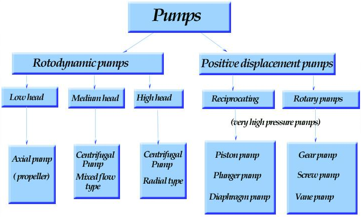
Fig.1. Pump classification.1
SUB-TYPE | DESCRIPTION | EXAMPLES |
Reciprocating Pump | Flow is established inside a cavity that expands and contracts, such as a piston. Water moves into the cavity during expansion, and is forced out during contraction, while the flow direction is controlled by using check valves. | Bladder |
Rotary Pump | This pump type uses a rotor that traps water in cavities, releasing it at the outlet. These cavities can be the spaces between gear teeth or screw threads, among other configurations. Some designs use more than one shaft, but the principle is the same: the rotor shape is designed to capture “pockets” of water and displace them in the intended direction. | Gear |
SUB-TYPE | DESCRIPTION | PERFORMANCE |
Axial Flow Pump | Also known as a propeller pump, it produces water flow along the impeller shaft direction. | High flow rate |
Radial Flow Pump | This pump type produces flow in a direction perpendicular to the shaft (90° angle). | Low flow rate |
Mixed Flow Pump | This pump type combines radial and axial flow, producing a conical flow pattern around the shaft. | Medium flow rate |
HEAT EXCHANEGR
TUBE SIDE HOT FLUID
2 DIFFERNET CHECK VALVES WILL PREVENT FLOW CASE BUT NOT PRESSURE CASE
SPECTACLE BLIND WHEN NOZZLE NOT IN USE
Canned Pump
Canned motor pumps are preferred
in the chemical and petrochemical industry, but also for simple pumping tasks,
such as circulating pumps in industrial refrigeration equipment.
In general, the following media
are conveyed: aggressive, toxic, explosive, hot, cryogenic, malodorous,
volatile, flammable or carcinogenic substances – in brief, media that represent
an environmental and health hazard.
Advantages of canned motor pumps at a glance:
·
Canned motors
are employed wherever hot,
aggressive, explosive, toxic or radioactive fluids need to be pumped, which is
why a great deal of focus is placed on hermetically sealed pump sets
without gland
packings or mechanical
seals. Canned motors
are used for circulators reactor circulating pumps
(see Reactor
pump), and process
pumps for
chemical and process engineering applications.
See Fig. 1 Canned motor
·

·
Fig. 1 Canned
motor pump: Single-stage volute casing pump for general industrial applications
Steam flooding
Stam inject and sweep oil to well
Canned – sump pump, not enough npsh, in our plant for
solvent (500-600 kg/m³)
Impeller under the ground, impeller of the pump is underground
to provide head for pump and suction
Solvent booster pumps are canned and solvent feed pump are
canned type
0012 I scanned pump to be used
Lean or rich gluycool can be water content , can be solvent
or water or gas content in gas or h2s or co2
Production crossover
ALL HEAT XCHNAGERSS ARE CONSIDERED AS A PRESSURE VESSEL SO
THEY HAVE A PSV AS PER THE ASME CODE ON BOTH SIDES
ALL VESSELS COZ OF THE ACCUMULATION PRESSURE WILL HAVE PRESSURE
CLASS CHANGE AT THE BOTTOM AND ITS BEST TO HAVE IT AT THE NOZZLE SINCE THE
NOZZLE WILL HAVE A PRESSURE CLASS CHANGE ANYWAYS

